The HVAC contractor at Coastal Mechanical Services presented his Miami hotel project bid on March 2023 while declaring an HVAC copper tube requirement of 12 pounds which he needed to acquire at a price that had remained unchanged for multiple years. The project commenced construction in August when copper futures prices reached $12 per pound which had been established as a fixed price. The project commenced construction in August when copper futures prices reached $18 per pound which caused an additional $47,000 expense because he had not included that amount in his fixed-price contract. His primary supplier did not have 7/8″ linesets available which he required for 5-ton units, which caused a three-week delay because of the need to find a different supplier. The copper tube he had treated as a commodity turned out to be the variable that erased his project margin.
The material used for HVAC copper tube installation requires special consideration because its apparent simplicity does not reflect its actual complexity. The specifications matter: ASTM B280 compliance affects system longevity. The system capacity and efficiency depend on line set sizing. The industry has experienced major changes in refrigerant compatibility since adopting R410A and now preparing for R32 introduction. Project schedules depend on supply chain conditions which have the power to either complete or disrupt work.
This guide provides the technical foundation for specifying, sizing, and installing HVAC copper tube correctly. You will understand the ASTM B280 requirements and learn how to design lines for various systems and study refrigerant compatibility and installation methods that will help you avoid the failures which occur when copper tube is treated as an afterthought. The principles presented here apply to contractors who bid on commercial projects, to engineers who create specifications and to maintenance technicians who solve system issues.
What is HVAC Copper Tube?
ASTM B280 ACR Tube Definition
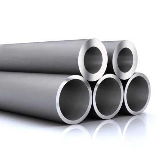
HVAC copper tube—properly called ACR (Air Conditioning and Refrigeration) tube—is manufactured to ASTM B280, the standard specification for seamless copper tube for air conditioning and refrigeration field service. This standard defines the chemical composition, mechanical properties, cleanliness requirements, and dimensions that distinguish ACR tube from plumbing or general-purpose copper tube.
Key characteristics of ASTM B280 HVAC copper tube:
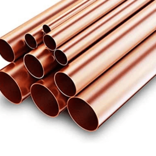
- Material: UNS C12200 (DHP—Deoxidized High Phosphorus) copper containing 99.9% copper minimum with 0.015-0.040% phosphorus
- Cleanliness: Interior surfaces must be clean, dry, and free of oil and oxides
- Packaging: Ends sealed with caps or crimps to prevent contamination ingress
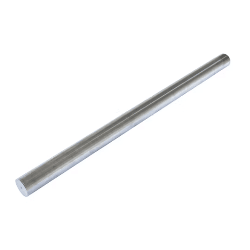
- Temper: Available in soft annealed (O60) for field bending or hard-drawn (H58) for rigid applications
The phosphorus content in C12200 provides deoxidation during manufacturing, resulting in tube with superior weldability and brazing characteristics compared to oxygen-bearing copper grades. This matters because HVAC systems rely on brazed joints—not soldered connections—to withstand refrigerant pressures.
Why ASTM B280 Matters for HVAC Systems
The cleanliness requirements in ASTM B280 exist for specific technical reasons that affect system performance:
Moisture exclusion: Residual moisture in copper tube reacts with refrigerant and oil to form acids that corrode compressor windings and system components. ASTM B280 requires dehydration and sealed packaging to maintain interior dryness.
Oil and contaminant removal: Manufacturing oils and particulate contamination can clog expansion valves and capillary tubes. The standard mandates cleaning processes that remove these contaminants.
Oxide prevention: Interior copper oxide flakes can circulate through the system, damaging compressor valves and coating heat transfer surfaces. Sealed ends prevent oxidation during storage.
Using plumbing-grade copper (ASTM B88) for refrigeration applications violates best practice because it lacks the cleanliness guarantees, sealed packaging, and dimensional tolerances that ASTM B280 requires. The cost savings are minimal; the failure risk is substantial.
HVAC Copper Tube Specifications

Standard Dimensions and Wall Thickness
HVAC copper tube is sized by outer diameter (OD) in fractional inches. The most common sizes and their applications:
| OD Size | Common Application | Metric Equivalent |
|---|---|---|
| 1/4″ (0.250″) | Capillary tubes, small line sets | 6.35mm |
| 3/8″ (0.375″) | Liquid lines, small suction lines | 9.52mm |
| 1/2″ (0.500″) | Suction lines (1-2 ton systems) | 12.7mm |
| 5/8″ (0.625″) | Suction lines (2-3 ton systems) | 15.88mm |
| 3/4″ (0.750″) | Suction lines (3-5 ton systems) | 19.05mm |
| 7/8″ (0.875″) | Large suction lines (5+ ton) | 22.23mm |
| 1-1/8″ (1.125″) | Commercial suction lines | 28.58mm |
Wall thickness varies by tube type. ASTM B280 specifies minimum wall thickness for each OD:
- Standard ACR tube: 0.030″ (0.76mm) minimum wall for 3/8″ through 7/8″
- Type K: Heaviest wall (0.049″ for 1/2″), used for high-pressure applications
- Type L: Medium wall (0.035″ for 1/2″), common for general HVAC
- Type ACR: Lightest wall, used for most residential and commercial systems
For R410A systems operating at higher pressures, Type K or L may be specified over standard ACR wall thickness for additional safety margin.
Temper Classifications for HVAC
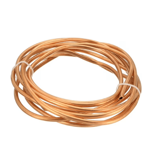
Soft Annealed (O60 temper):
- Fully annealed for maximum ductility
- Can be bent by hand or with simple tools
- Used for 90% of field installations
- Supplied in coils (pancake or level-wound)
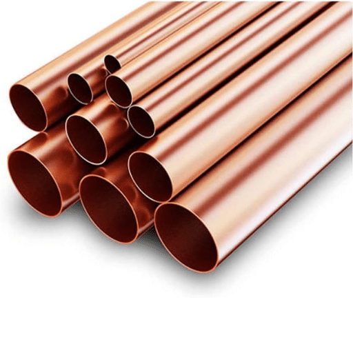
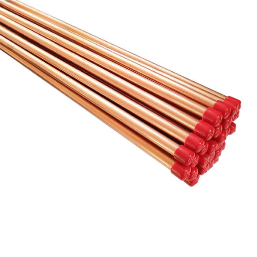
Hard Drawn (H58 temper):
- Work-hardened for rigidity
- Requires tube bender for any shaping
- Used for straight-line runs and structural applications
- Supplied in straight lengths (typically 20 feet)
The temper designation appears on ASTM B280 markings and determines how the tube is handled during installation. Soft temper is almost universally specified for residential and light commercial split systems where routing around obstacles is required.
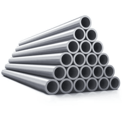
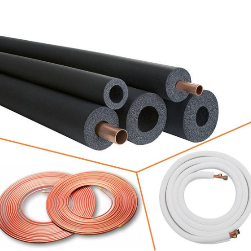
Coil Configurations
HVAC copper tube is supplied in two primary coil formats:
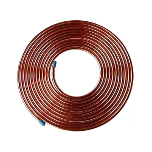
Pancake Coils:
- Individual coils of specific lengths (typically 15, 25, or 50 feet)
- Used for mini-split installations and short line set runs
- Easy to transport and handle on job sites
- Minimizes joints in the field
Level Wound Coils (LWC):
- Large coils containing 100-500+ feet of continuous tube
- Used for commercial installations and long line runs
- Requires uncoiling equipment for proper handling
- Cost-effective for high-volume installations
Zhongzheng supplies HVAC copper tube in both configurations, with pancake coils most common for residential mini-split and standard split system installations.
Line Set Sizing by Application

Residential AC Systems
Line set sizing directly affects system capacity, efficiency, and reliability. Undersized suction lines create excessive pressure drop, reducing capacity and potentially causing compressor overheating. Oversized liquid lines can create refrigerant velocity problems affecting oil return.
Standard Residential Sizing by System Tonnage:
| System Size | Suction Line (OD) | Liquid Line (OD) | Max Line Length |
|---|---|---|---|
| 1.0 – 1.5 ton | 1/2″ | 3/8″ | 50 feet |
| 2.0 ton | 5/8″ | 3/8″ | 75 feet |
| 2.5 – 3.0 ton | 3/4″ | 3/8″ | 75 feet |
| 3.5 – 4.0 ton | 3/4″ | 3/8″ | 100 feet |
| 5.0 ton | 7/8″ | 3/8″ | 100 feet |
Line Length Considerations:
- Standard ratings assume 25 feet of line set
- Capacity derating typically required beyond 50 feet
- Vertical rise adds additional refrigerant charge requirements
- Long lines may require suction line insulation upgrades
Always consult the equipment manufacturer’s installation manual for specific line set sizing—these tables provide general guidance, but OEM requirements take precedence.
Heat Pump Systems
Heat pumps place additional demands on line sets because the same piping must function in both heating and cooling modes:
Reversing Line Function: In cooling, the larger tube carries suction gas; in heating, it carries discharge gas. Both conditions must be evaluated for pressure drop and velocity.
Heating Mode Considerations:
- Discharge temperatures in heating can exceed 200°F (93°C)
- Suction line insulation is critical to prevent condensation and capacity loss
- Long lines in heating mode may require crankcase heaters to prevent refrigerant migration
Defrost Cycle Stress: Heat pumps periodically reverse to melt outdoor coil frost. This cycling creates thermal stress on line set joints and requires proper brazing technique to prevent failures.
Commercial VRF/VRV Systems
Variable Refrigerant Flow (VRF) or Variable Refrigerant Volume (VRV) systems use copper tube networks that differ from conventional split systems:
Multi-Zone Distribution: A single outdoor unit serves multiple indoor units through a network of branch controllers (Y-joints or headers). This requires:
- Careful sizing of main trunk lines based on total connected capacity
- Proper selection of branch line sizes for each indoor unit
- Oil return considerations with extended piping runs (some systems use oil separators)
Maximum Piping Lengths:
- Total equivalent length: typically 300-500 feet depending on manufacturer
- Vertical separation: 100-165 feet between outdoor and indoor units
- Farthest indoor unit: typically 300+ feet from outdoor unit
VRF line set sizing requires manufacturer-specific software calculations—rule-of-thumb sizing is insufficient for these systems.
Modern Refrigerant Compatibility

R410A Systems (Current Standard)
R410A has been the dominant refrigerant for new HVAC systems since 2010, replacing R22. Key characteristics affecting copper tube specification:
Higher Operating Pressures:
- Suction pressure: 100-150 PSIG (vs. 60-75 PSIG for R22)
- Discharge pressure: 400-550 PSIG (vs. 200-300 PSIG for R22)
- Requires pressure-rated copper tube and brazed joints
Oil Compatibility:
- R410A uses POE (Polyolester) oil instead of mineral oil
- POE oil is more hygroscopic (moisture-absorbing)
- Strict moisture control during installation is essential
Retrofit Considerations:
- R410A cannot be used in existing R22 systems (different oils, pressures)
- System replacement requires new line sets or thorough flushing
- Never mix refrigerants—contamination causes system damage
ASTM B280 copper tube is fully compatible with R410A. The higher pressures make proper brazing technique and leak testing more critical than with legacy refrigerants.
R32 Systems (Emerging)
R32 is gaining adoption as a lower-GWP (Global Warming Potential) alternative to R410A:
Mild Flammability:
- R32 is classified as A2L (mildly flammable)
- Requires adherence to charge limits per safety standards
- Ignition risk is low but requires awareness in installation
Material Compatibility:
- Copper tube: Fully compatible
- Elastomers: Some seals and gaskets require verification
- Refrigerant quality: Must be high-purity to prevent decomposition
Pressure Characteristics:
- Operating pressures similar to or slightly below R410A
- Existing ASTM B280 copper tube suitable without modification
Zhongzheng’s ASTM B280 copper tube is compatible with R32 systems. Specify the refrigerant at order to ensure appropriate packaging and documentation.
Natural Refrigerants (R290, CO2)
R290 (Propane):
- Hydrocarbon refrigerant with high flammability (A3 classification)
- Charge limits restrict use to small systems
- Copper tube compatibility: Excellent—traditional ACR tube fully suitable
- Leak detection and ventilation requirements more stringent
CO2 (R744) Transcritical Systems:
- Operates at extremely high pressures (1,500+ PSIG discharge)
- Requires heavy-wall copper tube or steel piping
- Standard ASTM B280 tube insufficient for transcritical CO2
- Specialized fittings and brazing procedures required
Future-Proofing Considerations: As environmental regulations tighten, specifying copper tube that meets ASTM B280 ensures compatibility with current and near-term refrigerants. For CO2 systems, consult specialized suppliers for pressure-rated materials.
Installation Best Practices
Pre-Installation Handling
Inspection Upon Receipt:
- Verify end caps are intact on all tube ends
- Check for physical damage (dents, kinks, corrosion)
- Confirm markings show ASTM B280 compliance
- Inspect coils for proper winding and banding
Storage Requirements:
- Store indoors, protected from weather
- Keep end caps in place until immediate installation
- Avoid contact with incompatible materials (dissimilar metals)
- Protect from contamination (dust, debris, chemicals)
Coil Uncoiling:
- Use uncoiling equipment for Level Wound Coils
- Avoid kinking—kinked tube must be cut out, never straightened
- Allow coil to relax before cutting to length
- Support coil weight to prevent ovality
Cutting and Preparation
Tube Cutter Selection:
- Use sharp, proper-sized tube cutters
- Avoid hacksaws (create metal particles and rough edges)
- For tight spaces, mini-cutters or scissor-type cutters work
Deburring:
- Deburr inside diameter (ID) to prevent turbulence and restriction
- Deburr outside diameter (OD) for proper joint fit
- Remove all chips and debris before brazing
End Preparation:
- Clean 1-2 inches beyond joint area with emery cloth
- Remove oxidation and contamination
- Avoid touching cleaned surfaces with bare hands (oil transfer)
Nitrogen Purging Procedure
Why Nitrogen Purge is Essential:
- Prevents internal oxidation during brazing
- Eliminates scale formation that contaminates the system
- Required for warranty compliance on most equipment
- Reduces compressor failure risk
Proper Purging Technique:
- Flow nitrogen at 2-5 CFH (cubic feet per hour)—low flow, continuous
- Purge both directions if possible
- Use a flow meter, not just pressure gauge
- Maintain flow during entire brazing process
- Continue 30 seconds after final joint cools
Common Mistakes:
- Using CO2 instead of nitrogen (creates carbonic acid)
- Insufficient flow rate (allows oxidation)
- Stopping purge before joints cool (draws air in through contraction)
- Not purging at all (guarantees system contamination)
Brazing Techniques for HVAC Copper
Alloy Selection:
- Silvabrite 15 (15% silver): Industry standard for R410A systems
- Silvabrite 56 (56% silver): Higher strength for high-pressure systems
- Phos-copper: Lower cost, acceptable for some applications
- Avoid soft solder: Cannot withstand refrigerant pressures
Brazing Procedure:
- Fit joints with proper clearance (0.002-0.005″ for slip joints)
- Apply flux sparingly to male end only (if required by alloy type)
- Heat evenly, directing flame away from expansion valves
- Add alloy when joint reaches temperature (red heat for copper)
- Allow capillary action to draw alloy into joint
- Do not overheat—burned flux causes joint failure
Post-Brazing:
- Allow natural cooling—do not quench with water
- Clean flux residue with wet rag (corrosive if left)
- Inspect joint for complete fill and no voids
Common Installation Errors and Prevention

Sizing Errors
Undersized Suction Lines:
- Excessive pressure drop reduces system capacity
- Causes compressor overheating
- Increases energy consumption
- Solution: Size per manufacturer specs, upsize for long runs
Oversized Liquid Lines:
- Low refrigerant velocity affects oil return
- Can cause compressor oil starvation
- Solution: Keep liquid lines 3/8″ unless manufacturer specifies larger
Long Line Set Compensation:
- Beyond 50 feet, capacity derating required
- Additional refrigerant charge needed
- Suction line insulation critical
- Consider line set sizing increase for very long runs
Installation Defects
Kinked Tubes:
- Creates flow restriction
- Causes pressure drop and capacity loss
- Can lead to tube failure at kink point
- Prevention: Proper bending technique, use of bend supports
Improper Support Spacing:
- Copper tube sags between supports
- Creates oil traps in suction lines
- Causes vibration and noise
- Standard: Support every 4-6 feet horizontally, every 10 feet vertically
Missing Insulation on Suction Lines:
- Causes condensation and water damage
- Reduces system capacity
- Creates efficiency loss
- Solution: 3/8″ wall closed-cell elastomeric insulation minimum
Contamination Issues
Moisture Ingress:
- From open tube ends during installation
- Causes acid formation and compressor damage
- Prevention: Keep caps on until ready to braze, purge with nitrogen
Debris from Poor Cutting:
- Metal chips from saw cutting
- Copper burrs not removed
- Causes TXV and compressor damage
- Prevention: Use tube cutters, proper deburring
Flux Residue:
- Corrosive if left in system
- Can clog small orifices
- Prevention: Clean joints after brazing, use minimal flux
Zhongzheng HVAC Copper Tube Capabilities

ASTM B280 Production Process
Zhongzheng’s copper tube manufacturing follows ASTM B280 requirements from cathode to finished product:
Raw Material: High-purity copper cathode (99.9%+) is melted and cast into billets. Phosphorus is added to create the DHP (deoxidized high phosphorus) composition that defines C12200 material.
Extrusion and Drawing: Billets are extruded into tube hollows, then drawn through dies to achieve precise OD and wall dimensions. Cold drawing work-hardens the material; subsequent annealing softens it to O60 temper for field bending.
In-Line Quality Control:
- Eddy current testing detects wall thickness variations and defects
- Dimensional verification ensures ASTM B280 tolerance compliance
- Surface inspection identifies cosmetic and structural issues
Pre-Shipment Preparation
Interior Dehydration: Tubes are internally dried to remove residual moisture. This process ensures compliance with ASTM B280 cleanliness requirements.
Nitrogen Charging: Each tube is charged with dry nitrogen and sealed with end caps. This positive pressure prevents air and moisture ingress during storage and transport.
End Cap Protection: Durable plastic caps protect tube ends from damage and contamination. Caps remain in place until installation, maintaining interior cleanliness.
Documentation Package: Each shipment includes material certification confirming ASTM B280 compliance, chemical composition, and dimensional test results.
HVAC-Specific Services
Custom Coil Lengths: Beyond standard pancake coil lengths, Zhongzheng can supply specific footage requirements to minimize field waste and joints.
Insulated Line Sets: Pre-insulated line sets with factory-applied closed-cell insulation reduce field labor and ensure proper insulation thickness.
Export Packaging: Moisture-barrier packaging, coil securing for sea freight, and end-cap protection for international shipment.
Frequently Asked Questions
What does ACR stand for in copper tubing?
The abbreviation ACR refers to “Air Conditioning and Refrigeration.” The designation ACR designates copper tubes which manufacturers produce according to ASTM B280 standards for HVAC/R applications. ACR tube differs from plumbing tube in cleanliness requirements (interior must be clean, dry, and free of oil), end sealing (caps to prevent contamination), and dimensional precision. ACR tube requires specification for refrigeration applications because plumbing tube cannot guarantee the necessary cleanliness standards which protect compressors and system components.
Can I use copper plumbing for HVAC applications?
No. Plumbing copper (ASTM B88) is not recommended for HVAC applications. The first difference between the two materials exists because ASTM B280 ACR tube requires specific cleanliness standards which must be maintained through its sealed ends that protect against contamination. The second difference exists because ACR tube undergoes dehydration and oil purification processes which prevent refrigerant control systems from becoming blocked. ACR tube markings identify the specific tube for warranty and inspection purposes. The interior of plumbing tubes contains oxides and contaminants which can harm compressors. The cost savings are minimal; the failure risk is substantial.
What is the maximum pressure for ASTM B280 copper tube?
The tube working pressure depends on three factors which are tube outer diameter and wall thickness and temperature. The standard Type ACR tube at 100°F operates with the following pressure limits: 3/8″ OD (0.030″ wall) ≈ 700 PSI; 1/2″ OD (0.030″ wall) ≈ 500 PSI; 7/8″ OD (0.032″ wall) ≈ 400 PSI. For higher pressure applications (R410A systems), specify Type K or L wall thickness. Burst pressure reaches approximately 3 to 4 times the working pressure. Safety factors must be applied according to the relevant codes, which typically require a 4:1 safety ratio for refrigeration systems.
How long can my line set be before I need to upsize?
The standard guidelines for Line set size show that manufacturers require standard sizes for distances up to 50 feet. The distance range between 50 to 75 feet requires suction line upsizing and capacity derating. The distance range between 75 to 100 feet requires one size larger suction line and major capacity changes. The system needs detailed calculation work because it exceeds 100 feet distance. Equipment manufacturers specifications should be consulted first because they serve as general guidelines. Long line sets require extra refrigerant charge calculations and needed suction line insulation work.
Does nitrogen purge serve as a requirement during the process of brazing copper.
Nitrogen purging during brazing is essential to prevent internal oxidation. The tube will develop copper oxide scale because oxygen enters through purge system. The scale flakes off and moves through the system which causes damage to compressor valves and TXVs while building up on heat transfer surfaces. HVAC best practice standards and equipment warranties make this practice necessary. Maintain continuous low-flow nitrogen usage at 2 to 5 CFH during the entire brazing procedure.
Can HVAC copper tube be used with propane (R290) refrigerant?
The copper tube according to ASTM B280 specification works perfectly with R290 propane refrigerant. R290 is a hydrocarbon which shows complete compatibility with materials because special copper requirements do not exist. R290 presents a high flammability hazard because it belongs to A3 classification. The installation requires the installation team to follow charge limits and leak detection standards and ventilation standards. ACR tube reaches full suitability for use because no changes are needed for the copper tube.
What distinguishes soft copper from hard copper when used in HVAC systems?
Soft copper (O60 temper) is annealed for maximum ductility and it serves as the primary material for 90 percent of HVAC installations because workers can bend it with their hands or basic tools to create routes that navigate around obstacles. Hard copper (H58 temper) exists as a work-hardened material which maintains its rigid form until workers use tube benders to shape it for use in straight runs and structural applications. Coils contain soft copper while hard copper exists in straight lengths. For split system installations, soft copper is almost always specified.
Conclusion: Specifying HVAC Copper Tube with Confidence
HVAC copper tube exists as a specialized material which impacts system performance and operational dependability and equipment lifespan. The ASTM B280 standard requires modern refrigerant systems to meet specific cleanliness and dimensional and material property requirements. The sizing of line sets establishes both the system performance and operational efficiency of the system. The correct installation methods stop both contamination and system breakdowns which lead to customer return visits and warranty service requests.
The key takeaways for specifying and installing HVAC copper tube:
- Specify ASTM B280 ACR tube—not plumbing tube—for all refrigeration applications
- Size line sets per manufacturer specifications, adjusting for line length and vertical rise
- Verify refrigerant compatibility—current R410A systems and emerging R32 systems both require attention to pressure ratings
- Follow installation best practices—nitrogen purging, proper brazing technique, and contamination prevention are non-negotiable
- Source from qualified suppliers with documented ASTM compliance and proper packaging
At Zhongzheng, our copper tube production follows ASTM B280 from cathode to finished coil. All tubes undergo eddy-current testing to detect defects, dehydration to achieve cleanliness standards, nitrogen charging, and the application of protective end caps. We provide HVAC copper tube which meets both standard pancake coil requirements for residential mini-splits and level-wound coil specifications for commercial VRF installations to ensure your project schedule remains protected.