A $127 roll of copper tubing destroyed a $12,000 commercial refrigeration system in Milwaukee last August. The contractor had used standard plumbing-grade copper instead of ASTM B280-compliant ACR tube. The system required R410A refrigerant pressure to operate, but non-dehydrated tubing produced microscopic particles that blocked the TXV, which caused superheated vapor to return to the compressor. At three weeks after startup, the scroll motor ceased to function.
Every cooling season sees this scenario repeat on job sites. The HVAC copper tube specification that arrives on your truck isn’t just a commodity; it’s a precision component that determines whether your system runs for twenty years or fails before the first warranty period ends. The installation fails when you choose wrong material specifications and temper specifications and cleanliness standards because skilled brazing cannot save the installation.
This guide provides the complete technical framework for specifying, sizing, and installing HVAC copper tube to ASTM B280 standards. The specification details and sizing methodology and quality verification procedures guarantee system reliability, which you will find in this document.
What is HVAC Copper Tube?
ASTM B280 ACR Tube Definition
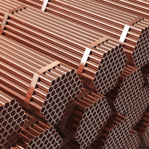
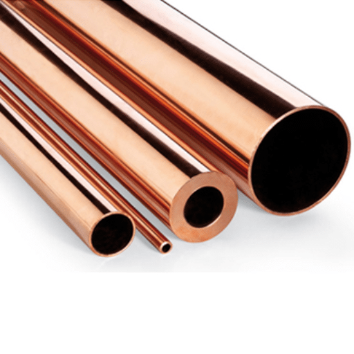
HVAC copper tube refers to seamless copper tubing manufactured specifically for air conditioning and refrigeration field service, governed by ASTM B280 standard specification. The material functions as C12200 DHP copper, which consists of a phosphorus-deoxidized copper alloy that contains 0.015 to 0.040 percent phosphorus to prevent oxygen and hydrogen embrittlement during brazing operations.
The critical differentiator between ASTM B280 copper tube and general-purpose plumbing tubing lies in cleanliness requirements. ACR (Air Conditioning & Refrigeration) tube must be internally dehydrated to remove residual moisture, sealed with nitrogen-charged caps at both ends, and maintained in a contamination-free condition through delivery. The specification exists because current refrigerant systems require parts-per-million tolerances for operation while 50 ppm moisture content can cause acid production which leads to compressor failure and system breakdown.
ASTM B280 specifies soft annealed temper (O60) as the standard delivery condition for field-bent installations, with light drawn temper (H58) available for structural applications where rigidity takes priority over formability. The standard covers outer diameters from 1/4 inch (6.35 mm) through 1-1/8 inch (28.58 mm), with wall thicknesses calculated to withstand refrigerant operating pressures while maintaining the thermal conductivity that makes copper the default material for heat transfer applications.
Why ASTM B280 Matters for HVAC
The refrigeration systems operate as closed-loop systems, which experience permanent damage from any contamination that enters their system. The HVAC refrigerant circuits operate with their single refrigerant charge being reused throughout the system approximately 6000 times every hour, in contrast to plumbing systems, which maintain constant water flow through their pipes. The system contains all installation materials, which include moisture, oxidation scale, and particulate matter, because these elements will continue to circulate through the compressor and expansion valve and heat exchanger coils of the system.
The mandatory cleanliness protocols established by ASTM B280 serve as established requirements for this matter. The tube interior needs to show visually complete cleanliness from dangerous deflects, which requires internal drying to eliminate both manufacturing waste and environmental moisture content and needs end caps to be securely sealed with either nitrogen or dry air pressurization. The intersection of the ASTM B280 tube should show an oxide-free copper surface, which waits for brazing after a contractor opens the tube which has been properly packaged.
The pressure rating requirements need to be treated as essential components of the system. The current R410A systems reach their operating pressure of 614 psig (43 bar) during 130°F of condensing, which exceeds the pressure of R22 systems by about 50%. The engineers who design ASTM B280 tube wall thicknesses create their products to protect both operational safety and thermal cycling, which happens during heat pump operation and defrost cycles through ongoing pressure tests.
ASTM B280 vs ASTM B88: Critical Differences
| Specification | ASTM B280 | ASTM B88 |
|---|---|---|
| Primary Application | Air conditioning & refrigeration | Potable water distribution |
| Cleanliness Requirement | Dehydrated, nitrogen-sealed ends | Standard mill finish, unsealed |
| Standard Temper | Soft annealed (O60) for bending | Hard drawn (H80) or soft (O60) |
| Interior Surface | Bright, oxide-free, moisture-free | Standard as-manufactured |
| Wall Thickness Designation | By OD with specified wall | Type K, L, M classification |
| Pressure Rating Basis | Refrigerant service temperatures | Water service at ambient temp |
| End Preparation | Sealed caps mandatory | Cut ends, no sealing |
The difference between the two standards has practical relevance beyond academic study. The use of ASTM B88 water tube in a refrigeration system results in moisture problems, scale accumulation, and introduction of foreign materials which ASTM B280 specifically prohibits. The cost of ASTM B280 tube products exceeds water tube products with matching dimensions by 15 to 20 percent because the dehydration process and nitrogen sealing and quality verification procedures for refrigerant service requirements drive up costs.
HVAC contractors should select specifications because all copper tubes which transport refrigerant need to comply with ASTM B280 standards. Water tube belongs in hydronic heating and domestic water systems where continuous flow prevents contamination accumulation. The combination of these two specifications creates a specific failure type which leads to complete compressor breakdowns that result in financial losses and damage to professional credibility.
HVAC Copper Tube Specifications

Standard Dimensions and Wall Thickness
ASTM B280 establishes consistent outer diameter dimensions across the industry, enabling interchangeability between manufacturers and compatibility with standard flare and compression fittings. The common OD sizes for residential and light commercial HVAC applications are:
| OD (inches) | OD (mm) | Nominal Wall (inches) | Min. Wall (inches) | Weight (lb/ft) | Max Working Pressure (psig) |
|---|---|---|---|---|---|
| 1/4 | 6.35 | 0.030 | 0.026 | 0.080 | 1,200 |
| 3/8 | 9.53 | 0.032 | 0.028 | 0.127 | 900 |
| 1/2 | 12.70 | 0.032 | 0.028 | 0.173 | 700 |
| 5/8 | 15.88 | 0.035 | 0.031 | 0.237 | 640 |
| 3/4 | 19.05 | 0.042 | 0.037 | 0.336 | 640 |
| 7/8 | 22.23 | 0.045 | 0.040 | 0.424 | 600 |
| 1-1/8 | 28.58 | 0.050 | 0.044 | 0.607 | 520 |
Pressure ratings calculated for annealed temper at 100°F with 4:1 safety factor per ASME B31.5
The wall thickness requirements exist to maintain pressure control while enabling thermal energy transmission. The system requires thicker walls to achieve higher pressure ratings, which creates a problem because heat transfer efficiency decreases according to this relationship in systems that handle big amounts of power because even small changes in BTU capacity affect system efficiency. The 3/8″ to 7/8″ tube size satisfies pressure requirements for R410A usage in residential settings because it allows refrigerant to evaporate at 45°F and condense at 120°F while delivering the thermal performance that industry standards require from copper.
International projects and OEM specifications now use metric measurements at an increasing rate. European and Asian manufacturers typically reference EN 12735-1 or JIS H3300 standards, which specify metric OD dimensions (6mm, 10mm, 12mm, 16mm, 19mm, 22mm) with slightly different wall thickness tolerances. The production facility at Zhongzheng offers both imperial ASTM B280 dimensions and metric standard dimensions, with cross-reference documentation provided for international procurement.
Temper Classifications for HVAC
Temper designation determines the mechanical properties that govern installation behavior and system performance. ASTM B280 specifies two primary tempers for ACR applications:
Soft Annealed (O60):The standard delivery condition for field installations requiring bending and routing around structural obstacles. O60 temper achieves ultimate tensile strength of 30,000 psi minimum with elongation exceeding 40%, providing the ductility needed for hand-bending or tube bender operations without cracking or splitting. The installation route for residential split system line sets needs this temper because it requires multiple direction changes.
Light Drawn (H58): A work-hardened condition provides greater rigidity for applications where tube straightness and structural stability take priority. H58 temper increases tensile strength to 45,000 psi minimum with reduced elongation of 15% minimum. This temper suits factory-assembled equipment connections, vertical risers in commercial installations, and applications where vibration resistance matters more than field formability.
The choice of temper affects how efficiently installation work proceeds. Contractors working with O60 soft copper can form bends as tight as 3× tube OD radius without specialized equipment, while H58 tube requires mechanical benders and larger bend radius to prevent wall thinning. The use of soft annealed tube for split system installations with long line sets leads to installation time reductions of 30 to 40 percent when compared with rigid alternatives.
Coil Configurations
HVAC copper tube is supplied in three primary formats, each optimized for specific installation scenarios:
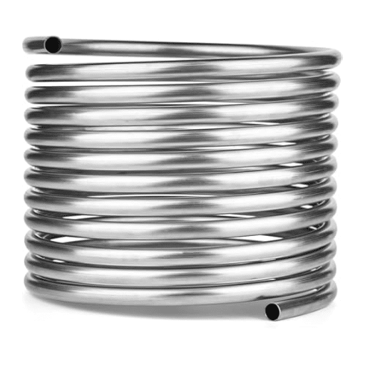
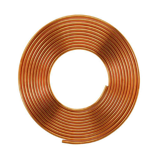
Pancake Coils: The flat spiral-wound coils have three standard lengths which are 15 feet, 25 feet and 50 feet. The pancake format is standard for mini-split installations, residential line sets, and repair applications where the tube must uncoil through finished walls or tight mechanical chases. The flat profile enables one-handed uncoiling while the installer routes the line through ceiling cavities or along framing members.
Level Wound Coils (LWC): The equipment consists of large-diameter cylindrical reels which hold 100 to 200 plus feet of uninterrupted tubing. The LWC format serves as the primary solution for commercial establishments, multi-unit residential developments and OEM manufacturing because it permits uninterrupted tubing runs without any need for field joints. The level wind pattern prevents tube-to-tube contact damage during transport and enables smooth pay-off during installation.
Straight Lengths: The equipment consists of two types of rigid material which include 10-foot and 20-foot sticks used to create short connections and equipment stub-outs and to connect devices which require straight lines. Straight lengths provide the most precise dimensional control and are preferred for shop fabrication of complex assemblies before field installation.
Zhongzheng supplies all three configurations of ASTM B280 copper tube which includes custom coil weights and lengths for specific project requirements. The export packaging system uses moisture barrier wrapping together with end-cap protection to preserve the required dehydrated sealed state which is essential for refrigerant service.
Line Set Sizing by Application

Residential AC Systems
Proper line set sizing balances refrigerant velocity against pressure drop, ensuring adequate oil return to the compressor while minimizing capacity loss. The Air Conditioning Contractors of America (ACCA) Manual D and manufacturer engineering data establish standard sizing protocols by system capacity:
| System Tonnage | Suction Line (inches) | Liquid Line (inches) | Max Line Length (ft) | Capacity Derating Beyond Max |
|---|---|---|---|---|
| 1.0 – 1.5 | 3/4 | 3/8 | 50 | 1% per 10 ft |
| 2.0 – 2.5 | 7/8 | 3/8 | 75 | 1% per 10 ft |
| 3.0 – 3.5 | 7/8 | 3/8 | 100 | 1% per 10 ft |
| 4.0 – 5.0 | 1-1/8 | 3/8 | 150 | 1% per 10 ft |
Sizing based on R410A refrigerant, 25 ft equivalent length, and proper elevation compensation
The suction line requires larger diameter because it transports refrigerant vapor from the evaporator to the compressor whereas the liquid line only needs to carry condensed refrigerant to the expansion valve. The system will suffer from excessive pressure drop because the suction line has been built too small which will lead to a system capacity loss of 5 to 10 percent while creating a danger of compressor overheating because of insufficient refrigerant flow through the system.
The process of sizing vertical risers requires extra factors to be considered. The suction line needs to be increased in size by one nominal dimension whenever it must carry vertical lifts that exceed 25 feet so that proper oil return flow can be achieved. The system must handle two distinct challenges when the condenser sits lower than the evaporator because the liquid line needs to handle both refrigerant subcooling and the prevention of flash gas in the vertical drop.
Heat Pump Systems
Heat pumps function as both heating and cooling systems which results in refrigerant lines experiencing extreme temperature and pressure conditions that exceed what cooling systems face. The outdoor coil operates as the evaporator during heating because its suction pressure drops to below 100 psig during cold weather conditions. The system needs special attention because its two-way operation requires specific requirements for both pipe dimensions and pipe protection.
Heat pump systems need to use the same pipe dimensions for their suction line as standard cooling systems require while their liquid line needs complete assessment. The former liquid line functions as the hot gas discharge line which transports compressor output to the indoor coil during heating mode. The system operates with reverse flow but needs both lines to withstand maximum pressure and temperature limits which occur during both operating modes.
Defrost cycles bring about short periods of thermal stress. The heat pump enters defrost mode which diverts hot gas to the outdoor coil for frost melting while it sends cold liquid back through lines that previously carried superheated vapor. The copper tube construction effectively handles thermal cycling when it receives proper support because its line hangers enable thermal expansion while maintaining minimal stress at brazed joints.
Commercial VRF/VRV Systems
Variable Refrigerant Flow (VRF) and Variable Refrigerant Volume (VRV) systems distribute refrigerant from a central outdoor unit to multiple indoor fan coils through extensive piping networks. The systems require special handling because they allow pipes to reach distances over 500 feet and vertical heights over 100 feet which creates engineering challenges that do not exist in ordinary home split systems.
Refrigerant Distribution: Multi-port headers and Y-joints divide refrigerant flow among multiple indoor units. The junctions need arc brazing technique and proper supporting to stop vibration from causing fatigue damage. The header tubing begins with a larger diameter which decreases to smaller sizes until it reaches the required size for each branch to work at the correct speed.
Oil Return Management: VRF compressors use refrigerant flow as the method to return system lubricating oil from the piping system. The system faces a danger of oil becoming trapped in its low sections when it uses extended horizontal line sets that have a slight slope. The engineering guidelines from the manufacturer establish both the minimum required velocities and the necessary line slope standards which should be set at 1:200 toward the compressor to enable oil to return uninterrupted.
Refrigerant Charge Calculations: Long line sets add significant refrigerant volume beyond the base equipment charge. VRF systems require precise accounting of line set volume to determine proper charging, with additional refrigerant added per foot of line length above manufacturer baseline. The improper charging of a system leads to a reduction in capacity while causing damage to the compressor and in very rare situations leads to liquid slugging situations.
Industrial Refrigeration Considerations
The specifications of industrial refrigeration systems exceed the capabilities of standard HVAC design. Food processing and cold storage facilities use ammonia (R717) systems which require different tubing materials because copper tubing becomes unusable when ammonia reacts with it to create copper-ammonia complexes which destroy the metal. The systems require stainless steel coil tubing or carbon steel piping which includes special corrosion protection features.
CO2 transcritical systems represent the opposite extreme. CO2 refrigeration systems need tubing which can withstand much higher pressures than the standard ASTM B280 dimensions because they operate at pressures which exceed 1,500 psig during gas cooler mode. The systems employ heavy-wall tubing and proprietary pressure-rated fittings that exceed the standard equipment requirements for HVAC copper materials.
Modern Refrigerant Compatibility

R410A Systems (Current Standard)
R410A has dominated the HVAC market since the R22 phase-out, operating at approximately 50% higher pressures than its predecessor. This pressure differential has direct implications for copper tube specification:
- Operating Pressures: R410A saturation pressure at 120°F condensing temperature reaches 614 psig, compared to 274 psig for R22 at equivalent conditions. The minimum design pressure for R410A system components is 550 psig, with test pressures typically 1.5× design pressure.
- Wall Thickness Verification: Standard ASTM B280 wall thicknesses provide adequate margin for R410A service at normal operating conditions. However, systems operating in high-ambient climates (Gulf Coast, Southwest desert) or with dirty condensers experiencing elevated discharge pressures should verify that the selected tube size maintains safety margins at worst-case conditions.
- Retrofit Considerations: Converting existing R22 systems to R410A (a practice generally discouraged by manufacturers due to compressor lubricant incompatibility) absolutely requires replacing the line set. The existing tubing, even if pressure-rated for R410A, contains residual mineral oil and potentially moisture that will destroy a POE-lubricated R410A compressor within weeks.
R32 Systems (Emerging)
R32 (difluoromethane) is becoming popular because it provides a lower-global warming potential option which competes against R410A that has a GWP of 675 while R410A has a GWP of 2088. This refrigerant operates at pressures 5–10% higher than R410A, within the same general range that standard ASTM B280 tube handles effectively.
The primary consideration for R32 is mild flammability (ASHRAE safety classification A2L). R32 demonstrates less flammability compared to hydrocarbon alternatives which include R290 yet installation procedures need to manage the possibility of ignition. Brazing operations require particular attention to leak testing, and mechanical rooms must meet ventilation requirements per ASHRAE Standard 15 and local building codes.
R32 requires no materials compatibility issues because it works well with copper tube systems. The refrigerant shows no corrosive properties and maintains chemical stability when exposed to copper and aluminum and common elastomeric materials. Systems designed for R410A can transition to R32 with minimal component changes, provided the manufacturer has validated the specific equipment for R32 service.
Natural Refrigerants (R290, CO2)
R290 (Propane): The hydrocarbon refrigerant demonstrates outstanding thermodynamic characteristics while its global warming potential (GWP) of 3 results in minimal environmental effects. The ASHRAE safety classification A3 (high flammability) restricts both the maximum charge limit and the operational usage of the substance. The R290 charge limit in residential and light commercial systems exists at 150 grams for each circuit which serves as an adequate amount for small split systems yet it falls short for larger systems.
The compatibility of copper tubes with R290 shows positive results because the two substances will not interact chemically with each other. The material challenge requires system designers to create R290 installations that need special construction methods and advanced safety systems in addition to normal HVAC requirements.
CO2 (R744) Transcritical: Carbon dioxide refrigeration operates in transcritical cycles at pressures far exceeding conventional refrigerants. The gas cooler outlets produce pressure values between 1,450 and 1,550 psig while the system experiences two thousand psig during warm weather conditions. The transcritical CO2 service requires standard ASTM B280 tubes which can handle working pressures below 700 psig, which do not meet the requirements.
The systems need pipes made from heavy-wall copper tube which has a wall thickness of 0.080 inch, or they must use proprietary steel pressure piping that requires special joining techniques. The copper tube applications in CO2 systems are limited to low-pressure side components and secondary coolant loops.
Refrigerant Transition Timeline
The U.S. EPA’s American Innovation and Manufacturing (AIM) Act mandates an 85% phasedown of HFC refrigerants by 2036, with specific GWP limits tightening progressively. For HVAC contractors and procurement managers, this transition creates specification uncertainty:
- 2025–2027: R410A remains available for equipment manufactured before regulatory cutoff dates. Service and replacement of existing systems continues with R410A.
- 2028–2030: New equipment transitions to A2L refrigerants (R32, R454B, R452B) with mildly flammable classifications. Training and certification requirements evolve to address A2L handling.
- 2030+: Low-GWP natural refrigerants gain market share in applications where safety constraints permit.
For copper tube procurement, this transition reinforces the importance of ASTM B280 compliance. Whether the refrigerant is R410A, R32, or emerging alternatives, the pressure ratings, cleanliness standards, and material specifications of ASTM B280 tube provide the foundation for reliable system operation.
Installation Best Practices

Pre-Installation Handling
ASTM B280 tube arrives with sealed, nitrogen-charged ends that must remain intact until immediately before brazing. Breaking these seals during transport or storage introduces atmospheric moisture and particulate contamination that defeats the standard’s purpose.
Inspection Protocol:
- Verify seal integrity on both ends before accepting delivery
- Check for visible damage to tube surface (scratches, dents, flat spots)
- Confirm coil labels match specification (ASTM B280, temper, OD, wall thickness)
- Store coils indoors, protected from moisture and temperature extremes
- Rotate stock: use oldest inventory first to minimize storage duration
When opening a coil for installation, cut the end cap carefully without driving debris into the tube interior. The tube end should be inspected through visual inspection which tests its brightness; an ASTM B280 tube that has been properly dehydrated should show a clear pink-copper surface which contains no oxidation discoloration. The presence of green corrosion together with dark scaling and visible moisture shows that the product has been stored improperly or is a fake item.
Cutting and Preparation
Tube cutting for HVAC applications requires tools that produce a clean, square cut without deforming the tube end. Standard copper tubing cutters with hardened steel wheels work effectively for soft annealed ASTM B280 tube. For larger diameters (3/4″ and above), ratchet-style cutters provide better leverage and cleaner cuts.
Cutting Procedure:
- Position the cutter square to the tube axis; angled cuts create gaps at brazed joints
- Tighten the cutter knob gradually, rotating the tool fully between each advance
- Continue until the tube separates cleanly without excessive force
- Remove the cut piece without dropping debris into the open end
Deburring Requirements: Internal burrs restrict refrigerant flow and create turbulence that generates noise and pressure drop. External burrs prevent proper fitting insertion and create gaps in brazed joints. Use a deburring tool designed for copper tube, inserting the internal blade fully and rotating 360° to remove all material raised by the cutting wheel. Brush away chips before proceeding to fitting preparation.
Nitrogen Purging Procedure
The single most critical installation practice that distinguishes professional HVAC work from failed installations is nitrogen purging during brazing. When copper reaches its brazing temperature of 1,100-1,300°F copper oxide scale develops through contact with oxygen. The oxide particles that result from this process will destroy compressor bearings and block expansion valves while they lead to major system breakdowns that occur several months after the system has been installed.
Nitrogen purging displaces oxygen from the interior of the tube during brazing, preventing oxidation. The procedure is non-negotiable for any brazed joint in a refrigerant system.
Purging Protocol:
- Connect a nitrogen cylinder with pressure regulator to one end of the line set
- Install a flowmeter or metering valve to control nitrogen flow rate
- Set flow to 3–5 SCFH (standard cubic feet per hour) for 3/8″–1/2″ tube, 5–8 SCFH for 5/8″–7/8″ tube
- Begin nitrogen flow before heating any joint
- Maintain flow continuously through the brazing operation
- Continue nitrogen flow for 30 seconds after the joint cools below 200°F
- Never increase flow to “cool” the joint faster; this causes internal oxidation
The nitrogen exiting the far end of the tube should remain steady throughout brazing. If flow stops or diminishes, check for kinks, closed valves, or blockage before continuing. Without positive nitrogen flow, oxidation occurs even if the tube interior appears protected.
Brazing Techniques for HVAC Copper
Brazing alloy selection for ASTM B280 tube requires attention to the phosphorus content of the copper itself. C12200 DHP copper contains 0.015–0.040% phosphorus, which can contribute to joint embrittlement when brazed with phosphorus-bearing filler metals in certain combinations.
Alloy Selection:
- BCuP Series (phosphorus-copper): Suitable for copper-to-copper joints where the phosphorus in the filler complements the base metal. BCuP-5 (15% silver) provides good flow characteristics and adequate strength for most HVAC applications.
- BAg Series (silver-copper-zinc): Required for copper-to-brass or copper-to-steel joints. BAg-1 (44–46% silver) offers excellent flow and capillary action; BAg-5 (44–46% silver, 30% copper, 26% zinc) provides higher strength for high-vibration applications.
- Avoid: Cadmium-bearing alloys (health hazard) and tin-lead solders (inadequate strength for refrigerant pressures)
Brazing Temperature Control:The copper tube wall starts to weaken through overheating while the excess zinc vaporizes from the filler alloy. A neutral flame must be used together with a slightly reducing flame which contains excess acetylene to achieve oxidation prevention. The fitting needs to be heated before the tube because capillary action will pull filler metal into the joint. A properly brazed joint shows complete filler flow around the fitting circumference with minimal excess buildup.
System Evacuation and Charging
After brazing is complete and nitrogen purge caps are removed, the system must be evacuated to remove atmospheric moisture and non-condensable gases before refrigerant charging.
Deep Vacuum Requirements:
- Target vacuum: 500 microns or lower
- Holding test: Vacuum should stabilize below 1,000 microns and hold for 30 minutes without rising more than 200 microns
- Evacuation method: Use a two-stage vacuum pump with adequate capacity (3–5 CFM minimum for residential systems, larger for commercial)
Moisture Removal: Water boils at room temperature under vacuum conditions which reach 29.9 inches Hg (approximately 5000 microns). The vacuum pump will eliminate all remaining installation moisture after reaching a vacuum level of 500 microns. The system needs to achieve deep vacuum because any remaining moisture will combine with refrigerant and lubricant to create acids.
Charging Procedures: The manufacturer specifications require weight-based refrigerant charging methods for all charging procedures. The charge quantity becomes known through weighing the refrigerant cylinder before and after the charging process. The system needs additional refrigerant for every foot of tubing that extends beyond the manufacturer’s base charge calculation in systems with long line sets. The system needs to demonstrate proper subcooling and superheat levels which must reach specific target ranges after it has reached operational stability.
Common Installation Errors and Prevention
Sizing Errors
Undersized Suction Lines : The system operates through refrigerant systems which require suction lines with their actual diameter as their minimum requirement because small diameter suction lines create high refrigerant flow rates. High velocity operation assists oil return but the system pressure drop causes both operational efficiency loss and higher compressor discharge temperatures. The system capacity loses 1 percent for every 2 psi decrease in suction line pressure. The compressor will experience overheating together with premature failure because undersizing creates extreme operational conditions.
Oversized Liquid Lines: The operation of liquid lines which have excessive dimensions results in insufficient refrigerant flow needed to transport oil through horizontal pipe sections. The system experiences oil accumulation at low points which decreases system charge and results in compressor lubrication deprivation. The oversized liquid lines increase the refrigerant charge requirements which may exceed the system limits and create slugging risks during the startup process.
Long Line Set Compensation: Manufacturer specifications assume typical line set lengths of 15–25 feet. The system capacity derating together with equipment upsizing requirements comes into effect when line sets reach distances beyond 50 feet. The systems require these adjustments because they need to achieve their maximum capacity together with their expected efficiency. For long line set applications you need to check manufacturer engineering data and you should upsize suction lines as necessary.
Installation Defects
Kinked Tubes: Sharp bends or kinks restrict refrigerant flow and create pressure drop. The restriction also generates noise as refrigerant accelerates through the narrowed section. Always use proper tube bending tools that support the tube wall during bending. Minimum bend radius is 3× tube OD for soft annealed copper; tighter bends risk wall thinning or collapse.
Improper Support Spacing: Copper tube expands and contracts with temperature changes. Inadequate support spacing allows sagging, which creates oil traps in suction lines and vibration-induced fatigue. Support horizontal lines every 4–6 feet and within 12 inches of direction changes. Use cushioned clamps that grip without crushing the tube; unlined metal clamps can damage copper surfaces and create corrosion initiation points.
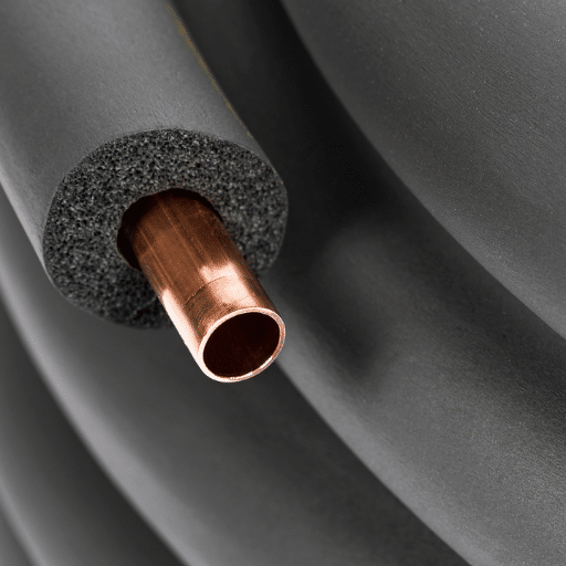
Missing Insulation: Suction lines must be fully insulated to prevent condensation and capacity loss. Exposed suction lines absorb heat from ambient air, reducing system efficiency by 5–15% depending on exposure extent. Use closed-cell insulation rated for the temperature range and UV exposure conditions. Seal all insulation joints with vapor barrier tape to prevent moisture migration.
Contamination Issues
Moisture Ingress: The process of breaking tube seals needs to take place before brazing work starts because this allows atmospheric moisture to enter the tubing. The 50 ppm threshold for acid formation gets exceeded because even short contact with material brings enough moisture to the system. The procedure requires immediate seal breaking before brazing while using nitrogen to purge the system whenever the open tube remains unattended for more than two minutes.
Debris from Poor Cutting: The use of hacksaws and abrasive wheels instead of tubing cutters creates copper particles and abrasive grit which contaminate the system. The compressor and expansion valve receive these particles which create damage that leads to system failures within several months. The organization needs to purchase suitable cutting equipment together with deburring methods.
Flux Residue: Excessive brazing flux left inside joints creates contamination that reacts with refrigerant. The procedure requires users to apply flux only to the fitting socket while they should avoid using it on both the tube exterior and joint interior. The process requires users to remove excess flux after brazing because warm flux is easier to clean than hardened flux which creates corrosion issues.
Quality Control and Testing

Zhongzheng HVAC Copper Production Process
The non-ferrous manufacturing expansion at Zhongzheng uses the same quality systems that originated from stainless steel precision tubing to produce ASTM B280 copper tubes. The process starts with teams conducting cathode copper verification which progresses until workers complete packaging dehydrated products through sealed containers.
Raw Material Verification: Production requires spectrographic analysis of each cathode copper heat before processing begins. The chemical composition must meet UNS C12200 specifications with phosphorus content in the 0.015–0.040% range. The documentation for material traceability includes records that show heat numbers and chemical analysis results with production lot assignments which create complete documentation packages.
Continuous Production Monitoring: Tube extrusion and drawing operations use in-line eddy current testing which detects wall thickness variations and internal defects and surface imperfections at production speed. The verification stations measure the outer diameter and wall thickness and ovality according to ASTM B280 tolerances which permit a deviation of ±0.003″ OD and ±10% wall thickness minimum.
Surface Quality Inspection: Visual inspection confirms bright, oxide-free interior surfaces required for refrigerant service. Any tube that displays discoloration or moisture spots or contamination gets rejected before it reaches the dehydration stage.
Pre-Shipment Preparation
The tube which receives approval undergoes internal drying through the application of heated and filtered air which eliminates all remaining moisture from its production process. The system requires a dewpoint of -40°F or lower to achieve moisture levels below 50 parts per million which would otherwise contaminate the refrigerant system.
The tube ends receive nitrogen pressurized sealing immediately after dehydration, which establishes nitrogen pressure to protect against moisture contamination during storage and transportation. The packaging process begins after all tubes go through pressure testing, which verifies their seal integrity through testing of all capped tubes.
Moisture-barrier film with desiccant packs protects coils and straight lengths from sea freight damage. The handling process of coils receives protection through wooden crates and steel frames, while end-cap protectors stop seal damage during loading and unloading operations.
Documentation Package
Each shipment of Zhongzheng ASTM B280 copper tube includes comprehensive documentation aligned with international project requirements:
- Mill Test Report (MTR): Chemical composition verification, dimensional inspection results, and compliance certification to ASTM B280
- Heat Traceability: Lot numbers linking finished product to raw material heat and chemical analysis
- Standard Compliance Certificate: Third-party verification of ASTM B280 conformance where specified
- Handling and Storage Instructions: Best practices for maintaining dehydrated, sealed condition through installation
Procurement and Logistics
Specifying HVAC Copper Requirements
Clear specifications ensure receipt of material that meets application requirements without costly substitutions or delays. Essential elements for ASTM B280 copper tube procurement include:
Material Designation: UNS C12200 (DHP copper) per ASTM B280 latest revision. Specify year if project requirements reference a specific standard version.
Dimensional Specification: OD, wall thickness, and temper (O60 soft annealed for field bending, H58 light drawn for rigid applications). Include tolerances if project requirements exceed ASTM B280 defaults.
Coil Configuration: Pancake coils for mini-split/residential, LWC for commercial/industrial, or straight lengths for fabrication shop use. Specify lengths or weights per coil.
Documentation Requirements: Standard MTR package or enhanced documentation with third-party inspection, EN 10204 3.1 certification, or project-specific test protocols.
Shipping and Handling
Copper tube packaging for international shipment must address the specific vulnerabilities of the material. Moisture exposure during sea freight can compromise dehydrated tube integrity, while handling damage can kink or deform soft annealed coils.
Zhongzheng’s export packaging protocol includes:
- VCI Barrier Wrapping: Volatile corrosion inhibitor film provides moisture barrier and active corrosion protection for sea freight duration
- Coil Securing: Steel banding and wooden frames prevent coil unwinding and handling damage during port operations
- End Cap Protection: Rigid protectors over nitrogen-charged seals prevent accidental puncture or pressure loss
- Humidity Indicators: Visual indicators inside packaging verify moisture barrier integrity upon receipt
Temperature considerations during transport are minimal; copper’s thermal stability exceeds any ambient conditions encountered in shipping. However, coils stored in freezing conditions should be allowed to reach installation temperature before uncoiling to prevent brittleness.
Lead Times and MOQ
Standard ASTM B280 copper tube in common sizes (3/8″, 1/2″, 5/8″, 3/4″, 7/8″) typically ships within 2–3 weeks of order confirmation. Custom dimensions, specialty tempers, or non-standard coil configurations require 4–6 weeks for production scheduling.
Minimum order quantities vary by product configuration:
| Configuration | Typical MOQ | Notes |
|---|---|---|
| Standard pancake coils (50 ft) | 50 coils per size | Mixed sizes acceptable within coil type |
| LWC (100–200 ft) | 20 coils per size | Longer lengths may require higher MOQ |
| Straight lengths (20 ft) | 100 pieces per size | Bundle quantities for efficient handling |
| Custom dimensions | Project-specific | Based on production run economics |
For project procurement, phased delivery scheduling aligns material arrival with construction milestones, reducing on-site storage requirements and contamination risks from extended outdoor exposure.
FAQs
What does ACR stand for in copper tubing?
The abbreviation ACR stands for Air Conditioning and Refrigeration which identifies ACR tube as copper tubing that meets ASTM B280 specifications through its dehydrated interior and sealed ends which make it suitable for refrigerant service. The designation identifies this product as a separate entity which meets refrigeration system cleanliness standards while plumbing-grade copper tube (ASTM B88) does not meet those standards.
Is plumbing-grade copper suitable for use in HVAC systems?
No. ASTM B88 plumbing copper lacks the dehydration, sealed-end protection, and interior cleanliness standards required for refrigerant systems. The introduction of plumbing copper brings both moisture and contaminants which lead to compressor failure and acid formation and system damage. Always specify ASTM B280 ACR tube for any refrigerant-bearing application.
What is the maximum allowable pressure for ASTM B280 copper tubing?
The maximum working pressure depends on both the tube dimensions and its temper characteristics. For common HVAC sizes in annealed (O60) temper: 1/4″ tube rates to 1,200 psig, 3/8″ to 900 psig, 1/2″ to 700 psig, 5/8″ to 640 psig, 3/4″ to 640 psig, and 7/8″ to 600 psig. The ratings include safety factors which remain valid up to 150°F temperature limit. The hard-drawn (H58) tempering method produces pipes with 40 percent higher pressure ratings but produces pipes which are less flexible.
How long can my line set be before I need to upsize?
The manufacturer guidelines establish different requirements but suction line systems should receive an upgrade when their equivalent length reaches 50 to 75 feet. The system needs a one nominal diameter increase when horizontal lines extend beyond 100 feet or vertical rises exceed 25 feet because this helps maintain proper refrigerant flow which is needed for oil return while reducing pressure drop capacity loss. The equipment manufacturer engineering data should be consulted to determine specific requirements for system upsizing.
Do I need to nitrogen purge when brazing copper?
Yes. The process of professional refrigeration installation requires nitrogen purging during the brazing process. The heated copper tube interior becomes oxidized without nitrogen flowing through it which results in scale formation that flakes off and moves through the system. The system contamination results in compressor and expansion valve damage. The nitrogen purge prevents oxidation by displacing oxygen from the tube interior during brazing operations.
Can HVAC copper tube be used with propane (R290) refrigerant?
Yes. Hydrocarbon refrigerants including R290 propane show complete compatibility with copper. The material considerations for R290 involve flammability safety systems, charge quantity limitations, and leak detection rather than copper compatibility. Standard ASTM B280 tube handles R290 pressures effectively, though system design must account for A3 flammability classification requirements.
What is the difference between soft and hard copper for HVAC?
The ductile properties of soft copper (O60 temper, annealed) enable users to bend the material using their hands or basic tube benders. The material maintains its straight shape through hard copper (H58 temper) which makes it suitable for applications that need structural support. Most HVAC field installations use soft copper; hard copper appears in pre-fabricated assemblies and straight-line applications.
Conclusion
The HVAC copper tube specifications require more than matching the tube diameter with the required fitting size. The standard ASTM B280 exists because refrigerant systems require cleanliness and pressure integrity and material consistency which general-purpose copper materials do not provide. ACR tube specifications contain all elements which maintain system reliability from phosphorus-deoxidized C12200 chemistry which prevents hydrogen embrittlement to dehydrated nitrogen-sealed packaging which keeps installation-ready condition.
The installation practices matter as much as the material. The combination of nitrogen purging during brazing with correct line sizing for capacity and oil return and deep vacuum evacuation and proper refrigerant charging creates professional installations which avoid callback failures that damage company reputation and profits. Contractors who master these details deliver systems that run for decades; those who skip steps face the type of catastrophic compressor failures that destroy customer relationships.
Zhongzheng applies the same precision manufacturing and quality verification systems that define our stainless steel production to ASTM B280 copper tube. The spectrographic verification of cathode copper together with dehydration and nitrogen charging and export packaging processes enables our HVAC copper products to comply with standards required for professional installations.