The validation engineer rejected your entire valve specification package with one note: “Ball valves are not acceptable for aseptic grade C areas.” Your selected valve type creates an un drainable dead zone which prevents cleanability qualification from being achieved after three weeks of procurement work. The process engineer requires sanitary diaphragm valves which have no dead leg design and complete CIP/SIP capabilities but your supplier catalog fails to explain the importance of diaphragm construction or provide guidelines for selecting proper membrane materials used in steam sterilization cycles.
Sanitary diaphragm valves provide aseptic pharmaceutical and food processing applications with hermetic sealing and drainable design features which ball and butterfly valves cannot deliver. Diaphragm valves use a flexible membrane which seals against a weir to create a self-draining flow path that clean-in-place (CIP) and steam-in-place (SIP) systems can fully validate whereas quarter-turn valves create product traps in their cavities and crevices. This guide provides the specification framework which establishes material selection criteria and quality verification requirements that process engineers and procurement teams need to specify sanitary diaphragm valves with confidence.
The course teaches you to differentiate between manual and pneumatic actuation for automated skids. The course shows you when PTFE diaphragms perform better than EPDM in aggressive media environments. The course demonstrates how to confirm actual 3A sanitary certification. The course teaches you why forged 316L valve bodies are essential for high-pressure steam sterilization cycles. This guide helps you select diaphragm valves which fulfill both process requirements and regulatory validation standards when you need to specify valves for either bioreactor harvest lines or UHT dairy pasteurizers.
What is a Sanitary Diaphragm Valve?
Valve Construction and Operating Principle
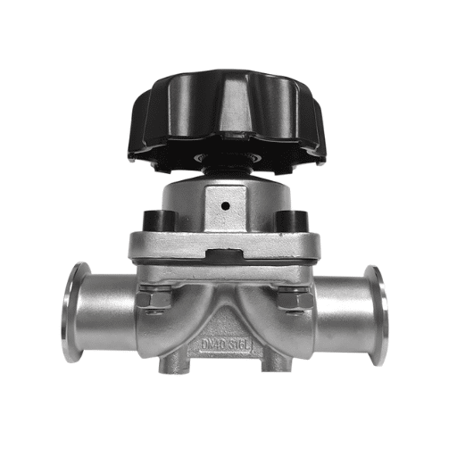
A sanitary diaphragm valve operates as a linear-motion valve which uses its flexible diaphragm membrane to keep process fluid separate from all mechanical parts of the valve operating system. The valve consists of three primary elements: a forged 316L stainless steel body with precision-machined weir or straight-through flow passages, a flexible diaphragm (PTFE, EPDM, or FKM) that forms the pressure boundary, and an actuator mechanism (manual handwheel or pneumatic piston) that compresses the diaphragm against the valve seat to modulate flow.
Diaphragm valves show only their diaphragm’s smooth surface to process fluid while both ball valves and butterfly valves use their respective internal mechanisms to control flow. The diaphragm generates a hermetic seal when it presses against a weir which the valve body contains because the seal contains no gaps or threads or pockets that would enable product accumulation. The diaphragm opens the valve when it lifts away from the weir because this action enables open flow through the valve body with only slight pressure loss.
This construction creates three critical advantages for aseptic applications:
Zero Dead Leg Design: The diaphragm seals flush against the valve body with no internal cavities, threads, or recesses. CIP fluid and SIP steam contact all process-wetted surfaces without trapped zones that resist cleaning.
External Working Parts: The valve stem and actuator components exist entirely outside the pressure boundary, isolated from the process fluid by the diaphragm. This eliminates packing glands and stem seals that can harbor contamination or leak externally.
Visual Leak Detection: Diaphragm failure results in visible external leakage at the weep hole, immediately alerting operators to seal compromise — unlike internal valve failures that may go undetected until product quality issues emerge.
3A Sanitary and ASME BPE Standards
Sanitary diaphragm valves for pharmaceutical and food processing must comply with recognized industry standards that define materials, surface finish, and cleanability requirements. The two primary standards governing sanitary valve specification are 3A Sanitary Standards and ASME BPE.
3A Sanitary Standards (administered by 3-A Sanitary Standards, Inc.) establish requirements for equipment used in dairy, food, and beverage processing. For diaphragm valves, 3A Standard 52-01 specifies:
- Materials: 316L stainless steel (UNS S31603) or equivalent corrosion-resistant alloy
- Surface finish: Maximum Ra 0.8μm (32 μin) on all product contact surfaces
- Design: No threads in product contact zones; all internal radii minimum 6mm for cleanability
- Diaphragm materials: Must be FDA-compliant for food contact under 21 CFR 177
ASME BPE (Bioprocessing Equipment standard) governs equipment for pharmaceutical and biotechnology manufacturing. ASME BPE-2022 provides:
- Material specifications with tighter controls on delta ferrite content for welded components
- Surface finish requirements: SF1 (Ra ≤ 0.51μm) or SF4 (Ra ≤ 0.38μm) depending on application criticality
- Documentation requirements for material traceability and testing
- Cleanability and drainability design criteria
Valves compliant with both 3A and ASME BPE standards carry dual certification, suitable for facilities manufacturing both food and pharmaceutical products under the same quality management system.
Why Diaphragm Design for Aseptic Applications
The pharmaceutical and food industries specify diaphragm valves for aseptic process lines because alternative valve types create validation and cleanability challenges that diaphragm construction eliminates.
Ball Valve Limitations: Ball valves use a rotating sphere which has internal flow passages to create seals. Even “sanitary” ball valves with polished surfaces create internal cavities and threads that trap product. The ball-to-seal interface requires precise torque for sealing, and worn seats allow internal leakage that CIP systems cannot detect or clean.
Butterfly Valve Limitations: The flow stream of butterfly valves uses a disc that creates a cleaning-resistant crevice between the disc and valve body. The stem seals required for butterfly valve actuation present potential leak paths and contamination risks. While acceptable for utility services and non-aseptic applications, butterfly valves rarely meet validation requirements for sterile product contact.
Diaphragm Valve Advantages: The diaphragm design eliminates all internal cavities, threads, and crevices from the process contact zone. The single-piece diaphragm membrane forms both the seal and the pressure boundary. CIP fluid flows across smooth, continuous surfaces. SIP steam penetrates all process-wetted areas without cold spots. The diaphragm replacement process allows users to restore the valve to its original condition because it requires no seat machining or regrinding.
Sanitary Diaphragm Valve vs Alternative Valve Types

Diaphragm vs Butterfly Valve Comparison
Process engineers frequently compare diaphragm and butterfly valves for sanitary applications. While both serve fluid control functions, their design principles create dramatically different performance in aseptic service.
Sanitary Diaphragm Valve vs Butterfly Valve Comparison
| Characteristic | Sanitary Diaphragm Valve | Sanitary Butterfly Valve |
|---|---|---|
| Cleanability | Excellent — smooth, cavity-free interior | Good — disc creates crevice requiring careful cleaning |
| Drainability | Excellent — self-draining when properly oriented | Good — disc pocket may retain liquid |
| Sealing Integrity | Excellent — diaphragm seals against weir | Good — elastomer seat wears over time |
| Pressure Rating | Moderate — typically 150-300 psi | Higher — up to 600+ psi depending on design |
| Flow Capacity | Moderate — weir creates some restriction | Excellent — full-bore flow when open |
| Cost | Higher — precision forging and diaphragm | Lower — simpler casting construction |
| Actuation Options | Manual, pneumatic, electric | Manual, pneumatic, electric |
| Validation Documentation | Extensive — 3A, ASME BPE, FDA materials | Standard — fewer aseptic certifications |
The implementation of butterfly valves should occur in situations that involve utility services which include water and steam and compressed air and CIP supply and return lines and non-aseptic process applications that require cost-effective solutions which exceed their maximum cleanability standards. Butterfly valves excel in high-flow systems which operate at lower criticality for their services.
Diaphragm valves become essential when they are needed for product contact lines which connect aseptic filling and bioreactor harvest and purified water distribution and all operations that need valid CIP/SIP and dead leg-free design. The regulatory guidance documents for pharmaceutical manufacturing now require diaphragm valves to be used in sterile product contact areas.
Diaphragm vs Ball Valve for Aseptic Service
Ball valves dominate industrial process applications, but their design creates fundamental cleanability challenges that disqualify them from most aseptic pharmaceutical services.
Ball Valve Cleanability Issues:
- Internal cavities in the ball trap product that CIP cannot fully remove
- Ball-to-body clearance zones create turbulent flow areas that resist cleaning validation
- Stem seals and packing glands present contamination risks
- Visual inspection cannot verify internal cleanliness
Diaphragm Valve Cleanability Advantages:
- Continuous, smooth interior surfaces with no internal cavities
- Straight-through flow path when fully open
- Diaphragm flexing during operation self-cleans the seal area
- Can be fully drained when installed with proper pitch
The pharmaceutical industry guidance documents (ISPE Baseline Guides, PDA Technical Reports) consistently recommend diaphragm valves over ball valves for sterile process applications. While ball valves remain acceptable for utility services and non-aseptic applications, diaphragm valves are the standard for product contact in aseptic processing.
When to Specify Diaphragm Over Other Designs
Specify sanitary diaphragm valves when your application meets any of these criteria:
Regulatory and Validation Drivers:
- Aseptic pharmaceutical manufacturing requiring validated CIP/SIP
- FDA-regulated food contact applications requiring 3A certification
- Bioprocessing applications with cell culture or protein products
- Purified water and water-for-injection (WFI) distribution systems
Process Requirements:
- Applications requiring visual confirmation of seal integrity
- Processes with high-value products where cross-contamination must be eliminated
- Systems requiring frequent cleaning cycles (multiple CIP/SIP per day)
- Applications with aggressive media that attack elastomer seats in other valve types
Quality and Risk Mitigation:
- Sterile product lines where a single contamination event costs millions
- Processes requiring decades of service life with minimal maintenance
- Applications where external leakage must be immediately visible
When other valve types are acceptable:
- Utility services (plant steam, cooling water, compressed air) where aseptic requirements do not apply
- Non-food-contact processes with lower cleanability requirements
- High-pressure applications exceeding diaphragm valve ratings
- Cost-constrained projects where validation requirements are minimal
Materials of Construction

316L Stainless Steel Body Forging Requirements
Sanitary diaphragm valve bodies are manufactured from 316L stainless steel (UNS S31603), the low-carbon variant of 316 that prevents sensitization and intergranular corrosion during welding and high-temperature sterilization cycles.
Chemical Composition Requirements:
- Chromium: 16.0-18.0% — corrosion resistance
- Nickel: 10.0-14.0% — austenite stability and toughness
- Molybdenum: 2.0-3.0% — chloride pitting resistance
- Carbon: ≤0.030% maximum — prevents carbide precipitation during welding
- Nitrogen: ≤0.10% — strength and corrosion resistance
Manufacturing Method: High-quality sanitary diaphragm valve bodies use forged rather than cast construction. Forging aligns the grain structure, eliminates internal porosity, and provides superior mechanical properties for pressure containment. Cast valve bodies may contain internal defects that create cleanability challenges and potential failure points under cyclic steam sterilization stress.
Surface Finish Specifications:
- Standard sanitary: Ra ≤ 0.8μm (32 μin) — 3A compliant
- High-purity pharmaceutical: Ra ≤ 0.51μm (20 μin) — ASME BPE SF1
- Ultra-high purity: Ra ≤ 0.38μm (15 μin) — ASME BPE SF4 with electropolishing
At Zhongzheng, sanitary diaphragm valve bodies are precision-forged from 316L billet stock, then CNC-machined to final dimensions with surface finishes meeting both 3A and ASME BPE requirements.
PTFE vs EPDM Diaphragm Material Selection
The diaphragm membrane is the critical component that determines valve chemical compatibility, temperature capability, and service life. Two materials dominate sanitary applications: PTFE (polytetrafluoroethylene) and EPDM (ethylene propylene diene monomer).
PTFE Diaphragm Characteristics:
- Chemical resistance: Virtually universal — resists all process chemicals except molten alkali metals and fluorinated compounds
- Temperature range: -40°C to 150°C (-40°F to 302°F)
- Flexibility: Rigid compared to elastomers; requires lower pressure ratings than EPDM
- Cost: Higher than EPDM
- Applications: Aggressive chemicals, solvents, high-purity water, pharmaceutical processes requiring broad chemical compatibility
EPDM Diaphragm Characteristics:
- Chemical resistance: Excellent for water, steam, and alkaline solutions; NOT compatible with oils, fats, or hydrocarbons
- Temperature range: -40°C to 130°C (-40°F to 266°F); steam service to 150°C intermittent
- Flexibility: Highly flexible; allows higher pressure ratings and more actuation cycles
- Cost: Lower than PTFE
- Applications: Water, steam, dairy, beverage, and pharmaceutical water systems where oils are not present
PTFE/EPDM Composite Diaphragms: Some manufacturers offer two-piece diaphragms with PTFE process contact surfaces laminated to EPDM backing. This construction provides PTFE chemical resistance with EPDM flexibility and pressure capability — ideal for high-purity applications requiring aggressive chemical resistance with steam sterilization.
Elastomer Compatibility and Temperature Limits
Selecting the correct diaphragm material requires matching elastomer properties to process conditions:
Chemical Compatibility Considerations:
- Oils and fats: PTFE only (EPDM swells and degrades)
- Steam and hot water: EPDM preferred (excellent steam resistance)
- Acids and bases: PTFE universal; EPDM good for dilute acids and bases
- Solvents: PTFE required (EPDM degrades in most organic solvents)
Temperature Service Limits:
- Continuous service temperature defines maximum operating limit
- Steam sterilization cycles may exceed continuous limits briefly
- Thermal cycling (hot CIP/cold product) accelerates diaphragm fatigue
Regulatory Compliance:
All diaphragm materials for food and pharmaceutical service must comply with:
- FDA 21 CFR 177 — indirect food additives
- USP Class VI — biological reactivity testing for pharmaceutical applications
- EU 1935/2004 — food contact materials regulation
Zhongzheng provides diaphragm material certifications with full traceability documentation, including FDA compliance letters and USP Class VI test results upon request.
Surface Finish Requirements (Ra ≤ 0.8μm)
Surface finish directly impacts cleanability, biofilm formation resistance, and validation success in pharmaceutical applications. Sanitary diaphragm valves must meet strict surface roughness specifications on all product-contact surfaces.
Surface Finish Definitions:
- Ra (Roughness Average): Arithmetic average of surface profile deviations from the mean line
- Lower Ra values indicate smoother surfaces with fewer microscopic peaks and valleys
- Pharmaceutical applications typically require Ra ≤ 0.8μm; high-purity applications may require Ra ≤ 0.4μm
Measurement and Verification:
- Profilometers measure Ra per ASME B46.1
- Surface finish certificates document actual measured values
- Electropolishing can reduce Ra by 30-50% from mechanical polishing baselines
Impact on Cleanability:
- Smoother surfaces (lower Ra) resist biofilm attachment
- CIP validation studies show improved cleaning efficiency below Ra 0.8μm
- Surface finish must be specified and verified for regulatory compliance
Design Variations and Configurations

Manual vs Pneumatic Actuation
Sanitary diaphragm valves operate with either manual handwheels or pneumatic actuators, with selection depending on automation requirements, speed of operation, and process criticality.
Manual Diaphragm Valves:
- Handwheel or T-handle operation for on/off service
- Position indicators show open/closed status
- Lower cost than pneumatic options
- Suitable for applications with infrequent operation
- Limit switch kits available for remote position indication
Pneumatic Diaphragm Valves:
- Air-to-open (normally closed) or air-to-close (normally open) configurations
- Fast actuation for automated process control
- Positioners available for modulating (throttling) service
- Solenoid valve integration for PLC control systems
- Spring-return failsafe options for critical safety applications
Actuator Sizing Considerations:
- Valve size (1/2″ to 4″) determines required actuator force
- Operating pressure (typically 60-80 psi air supply)
- Process pressure (higher line pressure requires larger actuators)
- Diaphragm material (PTFE requires more force than EPDM)
For automated skids and distributed control systems, pneumatic actuation with position feedback is standard. Manual valves suit utility services, sample points, and applications where automated control is not required.
Two-Way, Three-Way, and Multiport Designs
Sanitary diaphragm valves are available in multiple port configurations to suit different piping arrangements and process functions.
Two-Way Diaphragm Valves:
- Single inlet, single outlet
- On/off flow control
- Most common configuration for process lines
- Available in weir-style (better throttling) or straight-through (lower pressure drop)
Three-Way Diaphragm Valves:
- One common port and two selectable ports
- Diverting or mixing service
- Applications: Sample diversion, CIP divert, tank switching
- T-port or L-port flow patterns depending on function
Tank Bottom Valves:
- Specialized configuration for vessel drainage
- Valve body integrates with tank bottom flange
- Eliminates dead leg between tank and valve
- Critical for bioreactor harvest and tank drainage
Multiport Valve Blocks:
- Custom-manufactured blocks with multiple valve stations
- Reduces piping connections and potential leak points
- Common in chromatography skids and purification systems
Tank Bottom and Zero Dead Leg Configurations
Tank bottom valves represent a specialized diaphragm valve configuration designed to eliminate the dead leg between process vessels and drain valves.
Standard Valve Tank Connection Issue: A conventional valve installed on a tank nozzle creates a “dead leg” — the pipe section between the tank and the valve seat. This area traps product, resists cleaning, and creates validation challenges for aseptic systems.
Tank Bottom Valve Design:
- Valve body integrates directly with tank bottom flange
- Diaphragm seals flush with tank interior surface when closed
- No exposed piping between tank and valve seat
- Radial or tangential outlet configurations available
Regulatory Significance:
- FDA guidance documents recommend minimizing dead legs in aseptic systems
- ASME BPE defines maximum allowable dead leg dimensions (typically 3D rule — dead leg length no more than 3× pipe diameter)
- Tank bottom valves achieve zero dead leg compliance
Applications:
- Bioreactor harvest valves
- Fermentation tank drainage
- Purified water storage tank outlets
- CIP return connections
Connection Types (Tri-Clamp, Weld, DIN)
Sanitary diaphragm valves connect to process piping using standardized hygienic connection systems that ensure cleanability and seal integrity.
Tri-Clamp (Tri-Clover) Connections:
- Two ferrules with gasket, clamped with a single hinged clamp
- Most common connection in North American pharmaceutical and food plants
- Quick disassembly for maintenance and inspection
- 3A certified gaskets available in PTFE, EPDM, and silicone
- Sizes: 1/2″ to 4″ (DN15 to DN100)
Butt Weld Connections:
- Permanent welded connection to process piping
- No crevices or gasket interfaces
- Preferred for high-purity and permanent installations
- Requires orbital welding for quality assurance
- ASME BPE weld acceptance criteria apply
DIN 11850 Connections:
- European standard with male/female threaded union
- Common in European pharmaceutical facilities
- Available with various thread forms (DIN 11851, SMS, IDF, RJT)
- Metric sizing (DN15, DN20, DN25, etc.)
Selection Criteria:
- Tri-clamp: Applications requiring frequent disassembly
- Weld: Permanent installations with highest cleanability requirements
- DIN: European projects and equipment matching existing DIN infrastructure
Zhongzheng manufactures sanitary diaphragm valves with all standard connection types, with tri-clamp and weld configurations available from stock and DIN connections available on request.
CIP/SIP Process Integration

Clean-in-Place (CIP) Flow Dynamics
Clean-in-place systems rely on turbulent flow and chemical action to remove product residues from process equipment. Sanitary diaphragm valve design directly impacts CIP effectiveness and validation success.
CIP Flow Requirements:
- Minimum flow velocity: 1.5-2.0 m/s for turbulent cleaning action
- Temperature: Typically 65-80°C for alkaline wash cycles
- Chemical exposure: Caustic, acid, and rinse cycles
- Contact time: Sufficient duration for chemical action
Diaphragm Valve CIP Advantages:
- Smooth interior surfaces allow high-velocity flow without turbulence
- No internal cavities where cleaning solution can stagnate
- Diaphragm flexing during operation self-cleans the seal area
- Can be fully drained between steps when properly pitched
CIP Spray Ball Considerations:
For vessel connections, diaphragm valves must not obstruct spray ball patterns. Tank bottom valves with radial outlets maintain spray ball effectiveness while providing drainability.
Steam-in-Place (SIP) Sterilization Requirements
Steam-in-place sterilization kills microbial contaminants using saturated steam at temperatures typically 121°C (250°F) or higher. Sanitary diaphragm valves must withstand repeated thermal cycling while maintaining seal integrity.
SIP Cycle Parameters:
- Temperature: 121°C minimum (often 134°C for overkill sterilization)
- Pressure: 15-30 psi steam pressure
- Duration: 15-30 minutes at temperature
- Frequency: May occur multiple times daily in aseptic operations
Material Considerations for SIP:
- 316L valve bodies resist thermal stress and corrosion
- EPDM diaphragms handle steam well; PTFE also suitable
- Valve must tolerate thermal shock (steam to cold product transitions)
- Actuator materials must withstand valve body temperature during SIP
Condensate Management:
Steam traps and proper piping pitch ensure complete condensate drainage. Trapped condensate creates cold spots that prevent sterilization and allow microbial growth.
Drainability and Self-Draining Design
Pharmaceutical guidance documents emphasize the importance of complete drainability in process systems. Residual liquid in piping creates bioburden risks and cleaning validation challenges.
Self-Draining Design Principles:
- All process contact surfaces must drain completely by gravity
- No horizontal surfaces where liquid can pool
- Internal radii minimize liquid retention
- Valve orientation must allow complete drainage when closed
Installation Requirements:
- Install valves with proper pitch (minimum 1:100 slope)
- Orient valve so diaphragm weir is at lowest point when draining
- Avoid piping configurations that create liquid traps upstream of valves
- Verify drainage during commissioning with water rinse tests
ASME BPE Drainability Criteria:
- All product contact surfaces must be self-draining
- Internal angles must be ≥ 135° to prevent pooling
- Dead legs minimized or eliminated (3D rule compliance)
Validation Documentation Requirements
Pharmaceutical manufacturing requires extensive documentation demonstrating that equipment and processes consistently meet specifications. Sanitary diaphragm valves require specific documentation packages for validation.
Required Documentation:
- Material certificates: 316L heat numbers with chemical composition
- Surface finish certificates: Ra measurement reports
- Diaphragm certifications: FDA compliance, USP Class VI testing
- Calibration certificates: Pressure testing and dimensional verification
- Installation qualification (IQ): Verification of correct installation
- Operational qualification (OQ): Verification of operational ranges
- Performance qualification (PQ): Verification of process performance
Traceability Requirements:
- Valve serial numbers linked to material heat numbers
- Diaphragm lot numbers for replacement tracking
- Calibration and maintenance records
- Change control documentation for modifications
Zhongzheng provides comprehensive documentation packages for sanitary diaphragm valves, including material certifications, surface finish reports, pressure test certificates, and 3A compliance statements to support validation activities.
Applications by Industry

Pharmaceutical Bioprocessing
Pharmaceutical manufacturing presents the most stringent requirements for sanitary diaphragm valves, with regulatory oversight from FDA, EMA, and other agencies worldwide.
Upstream Applications:
- Bioreactor harvest valves (tank bottom configuration)
- Cell culture media addition lines
- pH adjustment and nutrient feed systems
- Sampling ports for in-process monitoring
Downstream Applications:
- Chromatography skid flow control
- Tangential flow filtration (TFF) systems
- Viral inactivation and purification steps
- Buffer preparation and hold tanks
Sterile Formulation and Filling:
- Formulation tank transfer lines
- Sterile filtration systems
- Aseptic filling line connections
- CIP/SIP system manifolds
Regulatory Drivers:
- FDA 21 CFR Part 211 (cGMP for finished pharmaceuticals)
- EMA GMP Annex 1 (manufacture of sterile medicinal products)
- ISPE Baseline Pharmaceutical Engineering Guides
- PDA Technical Reports for aseptic processing
In pharmaceutical applications, diaphragm valves are essentially mandatory for sterile product contact lines. The validation requirements for alternative valve types are prohibitively complex, making diaphragm construction the industry standard.
Food and Beverage Production
Food and beverage processing requires sanitary equipment that prevents microbiological contamination while withstanding aggressive cleaning chemicals and thermal processing.
Dairy Processing:
- Raw milk receiving and storage
- Pasteurizer connections (HTST and UHT systems)
- Culture and enzyme addition systems
- Clean-in-place manifolds
Beverage Production:
- Syrup and concentrate handling
- Carbonation systems
- Tank level control and transfer
- Yeast pitching and harvesting (breweries)
Food Processing:
- Sauce and dressing manufacturing
- Prepared food processing
- Ingredient addition systems
- Hot fill and cold fill packaging lines
Regulatory Framework:
- 3A Sanitary Standards for dairy and food equipment
- FDA Food Safety Modernization Act (FSMA)
- USDA requirements for meat and poultry processing
- HACCP principles for food safety management
Food applications typically use EPDM diaphragms for water and steam service, with PTFE specified for acidic or oily products. 3A certification is the primary specification requirement.
Cosmetics and Personal Care
Cosmetics manufacturing shares many sanitary requirements with pharmaceutical production, particularly for products applied to mucous membranes or intended for infant use.
Application Areas:
- Cream and lotion manufacturing
- Shampoo and conditioner production
- Oral care products (toothpaste, mouthwash)
- Baby care products (high purity requirements)
Quality Standards:
- ISO 22716 (cosmetics GMP)
- FDA regulations for cosmetics
- EU Cosmetics Regulation (EC) No 1223/2009
While cosmetics applications may not require the same validation rigor as pharmaceuticals, many manufacturers adopt pharmaceutical-grade equipment to ensure product quality and simplify regulatory compliance.
Biotechnology and Cell Culture
Biotechnology applications involving cell culture, fermentation, and biological production require equipment that maintains sterility while providing precise process control.
Cell Culture Applications:
- Seed train bioreactor connections
- Production bioreactor controls
- Cell retention and perfusion systems
- Harvest and clarification steps
Fermentation Applications:
- Microbial fermentation vessels
- Nutrient and pH control systems
- Product recovery and purification
- CIP/SIP system components
Cell and Gene Therapy:
- Closed system manufacturing
- Single-use technology integration
- Aseptic connection and disconnection
- Containment and biosafety systems
The growing cell and gene therapy sector drives demand for sanitary diaphragm valves that integrate with single-use technologies while maintaining traditional stainless steel reliability for permanent infrastructure.
Sizing and Specification

Valve Sizing by Pipe Diameter (1/2″ to 4″)
Sanitary diaphragm valves are standardized to match common hygienic piping sizes. Correct sizing ensures proper flow capacity and cleanability.
Standard Size Range:
- 1/2″ (DN15): Laboratory scale, sampling, small tank connections
- 3/4″ (DN20): Pilot scale, small process lines
- 1″ (DN25): Common process line size for many applications
- 1-1/2″ (DN40): Larger process flows, CIP supply lines
- 2″ (DN50): Main process lines, tank inlets/outlets
- 3″ (DN80): Large volume transfer, vessel connections
- 4″ (DN100): Maximum standard size, large tank applications
Sizing Considerations:
- Match valve size to piping for full-bore flow when open
- Consider future capacity expansion when selecting
- Larger valves cost more but reduce pressure drop
- Smaller valves may create flow restrictions in CIP circuits
Zhongzheng manufactures sanitary diaphragm valves in all standard sizes from 1/2″ to 4″, with 1″, 1-1/2″, and 2″ sizes typically available from stock.
Flow Coefficient (Cv) Considerations
The flow coefficient (Cv) quantifies valve flow capacity — the gallons per minute of water that will flow through the valve with a 1 psi pressure drop. Understanding Cv ensures proper valve sizing for process requirements.
Cv Values for Sanitary Diaphragm Valves (typical ranges):
- 1/2″ valve: Cv 4-6
- 1″ valve: Cv 15-20
- 2″ valve: Cv 55-70
- 4″ valve: Cv 220-280
Cv Selection Factors:
- Process flow rate requirements
- Acceptable pressure drop across valve
- Pump capacity and system pressure
- Future capacity expansion needs
Weir-Style vs Straight-Through: Weir-style diaphragm valves have lower Cv values (more restriction) than straight-through designs. Specify straight-through configuration for applications where pressure drop must be minimized.
Pressure and Temperature Ratings
Sanitary diaphragm valves have defined operating limits that must not be exceeded to ensure safe, reliable service.
Typical Pressure Ratings:
- Standard sanitary diaphragm valves: 150 psi (10 bar) at ambient temperature
- High-pressure designs: 300 psi (20 bar) with reinforced diaphragms
- Vacuum service: Full vacuum capability for most designs
Temperature Limitations:
- EPDM diaphragm: -40°C to 130°C continuous; 150°C intermittent (steam)
- PTFE diaphragm: -40°C to 150°C continuous
- 316L valve body: -196°C to 400°C (diaphragm limits actual service)
Combined Pressure-Temperature Ratings:
Valve ratings decrease at elevated temperatures. Consult manufacturer derating curves for applications above 100°C. Steam service at 150°C typically limits pressure to 100-125 psi depending on valve design.
Actuator Sizing for Pneumatic Valves
Proper actuator sizing ensures reliable valve operation under all process conditions.
Sizing Parameters:
- Valve size and diaphragm area
- Process pressure (higher pressure requires more actuator force)
- Diaphragm material (PTFE requires ~30% more force than EPDM)
- Operating speed requirements
- Air supply pressure available
Actuator Types:
- Linear piston actuators: Most common for diaphragm valves
- Rack and pinion: Compact design for smaller valves
- Double-acting: Air pressure opens and closes
- Spring-return: Spring provides failsafe position on air failure
Failsafe Selection:
- Air-to-open (normally closed): Valve closes on air failure — common for tank outlet applications
- Air-to-close (normally open): Valve opens on air failure — used for cooling water and some safety applications
Installation and Maintenance

Proper Installation Orientation
Correct valve installation ensures drainability, operability, and long service life.
Orientation Requirements:
- Install valve with stem vertical when possible (horizontal stem acceptable with proper support)
- Orient valve body so weir drains completely when closed
- Maintain minimum 1:100 pitch toward valve for drainage
- Provide adequate clearance for diaphragm replacement
Piping Support:
- Support piping independently of valve to prevent stress
- Use flexible connections or proper pipe supports near valve
- Avoid valve installation at piping stress points
Actuator Clearance:
- Ensure sufficient overhead clearance for actuator removal
- Consider actuator height in skid and panel layouts
- Provide access for pneumatic connection and maintenance
Diaphragm Replacement Procedures
Diaphragm replacement is the primary maintenance requirement for sanitary diaphragm valves. Proper procedure ensures seal integrity and prevents contamination.
Replacement Frequency:
- Typical service life: 1-3 years depending on cycling frequency and process conditions
- Visual inspection: Check for cracks, deformation, or wear
- Preventive replacement: Schedule during planned maintenance shutdowns
Replacement Procedure:
- Isolate and depressurize valve
- Remove actuator or handwheel assembly
- Remove diaphragm retaining components
- Inspect valve body sealing surfaces for damage
- Install new diaphragm (verify correct material and orientation)
- Reassemble and torque to manufacturer specifications
- Pressure test before returning to service
Critical Considerations:
- Use only manufacturer-specified diaphragms
- Verify material compatibility with process
- Follow torque specifications precisely
- Document replacement in maintenance records
Preventive Maintenance Schedules
Regular maintenance extends valve life and prevents unexpected failures that could contaminate product or shut down production.
Daily/Weekly Checks:
- Visual inspection for external leakage at weep holes
- Verification of proper operation (no binding or sticking)
- Pneumatic system checks for air leaks
Monthly/Quarterly Inspections:
- Diaphragm condition assessment
- Actuator operation verification
- Seal integrity testing
- Calibration verification for positioners
Annual Maintenance:
- Complete valve disassembly and inspection
- Surface finish verification if required
- Replacement of wear components (diaphragms, seals)
- Documentation update and traceability verification
Condition Monitoring:
- Track cycle counts for predictive replacement
- Monitor air consumption for pneumatic actuators (increased consumption indicates seal wear)
- Document any process upsets that may accelerate wear
Troubleshooting Common Issues
Understanding common valve problems enables rapid diagnosis and correction.
External Leakage at Weep Hole:
- Cause: Diaphragm failure or damage
- Solution: Replace diaphragm immediately
- Prevention: Use correct material; avoid over-torque during installation
Internal Leakage (Valve Won’t Seal):
- Cause: Debris on weir, damaged diaphragm, insufficient actuator force
- Solution: Clean valve body; replace diaphragm; verify actuator sizing
- Prevention: Proper filtration; scheduled diaphragm replacement
Sticking or Binding Operation:
- Cause: Product buildup, bent stem, misalignment
- Solution: Clean and inspect; replace damaged components; verify alignment
- Prevention: Proper CIP procedures; avoid piping stress on valve
Actuator Malfunction:
- Cause: Air supply issues, solenoid failure, positioner problems
- Solution: Check air pressure and quality; test electrical components; calibrate positioner
- Prevention: Filtered, dry air supply; regular calibration checks
Quality Verification and Procurement

3A Sanitary Certification Requirements
Third-party certification ensures that sanitary diaphragm valves meet recognized industry standards for materials, design, and cleanability.
3A Certification Process:
- Manufacturer submits valve designs to 3A for review
- Independent third-party verification of compliance with 3A standards
- Authorized use of 3A symbol on certified products
- Annual audits of manufacturing facility
What 3A Certification Verifies:
- Materials meet 3A requirements (316L stainless steel, FDA-compliant elastomers)
- Surface finish meets Ra ≤ 0.8μm requirement
- Design has no threads in product contact zones
- Minimum radii requirements met for cleanability
Limitations:
- 3A certifies design compliance, not manufacturing quality
- Individual valve quality depends on manufacturer’s QC
- Certificate applies to design, not specific production run
Verification: Request 3A certificate number and verify validity with 3-A Sanitary Standards, Inc. if authenticity is questioned.
Material Traceability Documentation
Pharmaceutical and food manufacturers require documentation tracing valve materials from raw stock through finished product.
Required Documentation:
- Mill Test Reports (MTRs) for 316L valve body material
- Heat numbers linking raw material to finished valve
- Chemical composition verification
- Mechanical properties (when applicable)
- Diaphragm material certifications (FDA, USP Class VI)
Traceability Chain:
- Raw material mill → heat number assigned
- Forging/machining → heat number transferred to valve body
- Assembly → valve serial number linked to body heat number and diaphragm lot
- Shipment → documentation package includes all traceability records
Records Retention: Pharmaceutical validation requires traceability records be maintained for the service life of the equipment — typically 10+ years.
Surface Finish Verification
Surface finish directly impacts cleanability validation and must be verified and documented.
Verification Methods:
- Profilometer measurement per ASME B46.1
- Surface roughness comparison standards
- Documented Ra values on all product contact surfaces
Sampling Requirements:
- Statistical sampling of production runs
- Critical surfaces (weir, sealing surfaces) 100% inspection
- Documentation of measurement locations and values
Acceptance Criteria:
- Standard sanitary: Ra ≤ 0.8μm (32 μin)
- High-purity: Ra ≤ 0.51μm (20 μin)
- Electropolished: Ra ≤ 0.38μm (15 μin)
Pressure Testing Protocols
Hydrostatic pressure testing verifies valve pressure boundary integrity before shipment.
Test Requirements:
- Test pressure: 1.5× rated working pressure (typical)
- Test duration: Minimum 60 seconds hold time
- Acceptance criteria: No visible leakage, no permanent deformation
- Test medium: Water (pneumatic testing only if water prohibited)
Documentation:
- Test pressure recorded
- Test date and technician identification
- Valve serial number linkage
- Pass/fail determination
Third-Party Witness: For critical applications, third-party inspection agencies (SGS, Bureau Veritas, TÜV) can witness testing and certify results.
Zhongzheng performs 100% pressure testing on all sanitary diaphragm valves, with test certificates included in standard documentation packages. Third-party witness testing is available upon request for project-specific quality plans.
FAQ
What is the difference between weir-style and straight-through diaphragm valves?
Weir-style diaphragm valves feature a raised weir machined into the valve body. The weir serves as the sealing point for the diaphragm when the valve is in its closed position. The weir design provides excellent throttling capability and is the standard for most sanitary applications. Straight-through diaphragm valves use a flat valve body design which lacks a weir system to achieve lower pressure drop and higher flow capacity with less accurate flow control. Use weir-style valves for modulating service and process control while using straight-through valves for on/off service which needs minimum pressure drop.
How long do PTFE and EPDM diaphragms last in pharmaceutical service?
The operating life of a diaphragm depends on three factors which include cycling frequency process temperature and chemical exposure. Pharmaceutical applications show a typical service life which lasts between 1 and 3 years. Equipment that operates multiple times each day needs its parts to be replaced every year. PTFE diaphragms last longer than EPDM diaphragms for chemical service but they need to be replaced more frequently during applications that involve high-flex cycling. Track cycle counts and implement preventive replacement schedules during planned maintenance shutdowns rather than waiting for failure.
Can sanitary diaphragm valves be used in high-vacuum applications?
Yes vacuum service is an appropriate application for sanitary diaphragm valves. The diaphragm design provides excellent vacuum sealing because it uses a packing gland-free system which blocks all air leakage paths. Valves should be specified according to their vacuum service rating because high vacuum applications need special diaphragm designs that prevent ballooning and distortion. Most standard sanitary diaphragm valves are rated for full vacuum (29.9 inHg) when properly specified.
What is the maximum steam sterilization temperature for diaphragm valves?
EPDM diaphragms handle continuous steam service up to 130°C (266°F) and intermittent exposure to 150°C (302°F). The PTFE diaphragms handle continuous operation until they reach 150°C (302°F) The two materials operate properly during steam sterilization at 134°C (273°F) overkill cycles, but EPDM material receives preference because it maintains flexibility while delivering superior sealing performance at elevated temperatures. The manufacturer needs to confirm specific ratings since diaphragm construction depends on both fabric reinforcement and thickness to determine temperature limits.
What process should I follow to confirm that a sanitary diaphragm valve possesses authentic 3A certification?
The 3A certificate number from the manufacturer should be requested, which should then be validated through 3-A Sanitary Standards, Inc. The certificate needs to list the specific valve model which it covers. Some manufacturers use the terms “3A design” and “3A compliant” to promote their products, yet these products lack actual third-party certification. The 3A symbol may only be used by valves which possess valid 3A certificates. All material certifications and surface finish reports and pressure test documentation need to be requested to establish that production quality meets the requirements of the certified design.
Do diaphragm valves function as effective devices for controlling flow through throttling and modulating operations?
Weir-style diaphragm valves provide reasonable throttling capability for sanitary applications, though they are not precision control valves. For modulating service, specify pneumatic actuators with positioners that maintain setpoint positioning. The weir design provides better flow control characteristics than straight-through designs. For precise flow control requirements (±1% accuracy), consider specialized sanitary control valves rather than standard diaphragm valves. The main purpose of sanitary diaphragm valves in most process applications involves performing either on/off operations or rough throttling procedures instead of executing precise modulating functions.
What maintenance is required for pneumatic diaphragm valve actuators?
Pneumatic actuators need basic maintenance which includes two essential tasks: (1) Ensure clean, dry air supply — install filters and dryers in the air system to prevent contamination and corrosion; (2) Lubricate per manufacturer schedule if the actuator requires lubrication (many modern actuators are pre-lubricated for life); (3) Check and calibrate positioners annually; (4) Inspect air lines and fittings for leaks during routine maintenance; (5) Verify emergency shutdown function for spring-return actuators.
Conclusion
Sanitary diaphragm valves deliver three essential features which aseptic pharmaceutical and food processing applications require for their operations. The specification choices which include PTFE and EPDM diaphragm materials together with system control methods and connection types between tri-clamp and weld connections will decide whether your valve system achieves validation or results in expensive delays during the start-up process.
Key specification takeaways:
- Specify PTFE diaphragms for chemical resistance; EPDM for steam and water service
- Use tank bottom valves for vessel connections to eliminate dead legs
- Verify true 3A certification through certificate validation, not marketing claims
- Require Ra ≤ 0.8μm surface finish with documented measurement reports
- Plan diaphragm replacement every 1-3 years based on cycle count, not failure